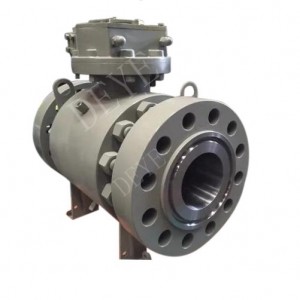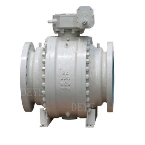
API6D trunnion Mounted Reducing Ball valve
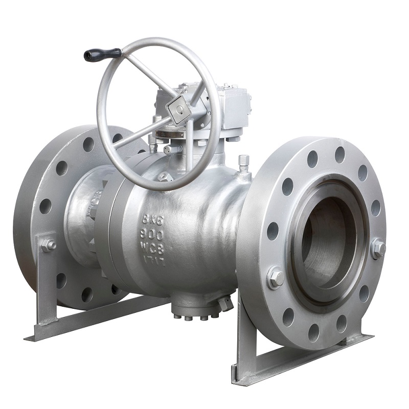

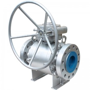
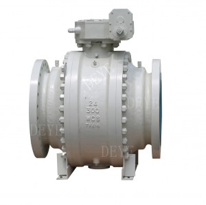
Carbon Steel A216WCB Trunnion Mounted Ball valve with reducing bore, API6D/API600
Size Range 4″-36″
Working Pressure: 150LBS-1500LBS
Design Details:
?STEEL BALL VALVES API 609/API 6D
?ANTI STATIC, API 608
?STEEL VALVES, ASME B16.34
?FACE TO FACE, ASME B16.10
?END FLANGES, ASME B 16.5
BUTTWELDING ENDS, ASME B 16.25
?INSPECTION AND TEST, API 598/API 6D
?STEEL BALL VALVE ISO 14313
?FIRE SAFE, API 607
Features
?Reducing Bore or Full bore Design
?Bolted Bonnet /Split Body
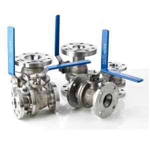
?Trunnion Mounted Ball or Floating Ball type
?BLOW-OUT proof? Stem
? Fire Duable Constuction
?Antistatic Device
??Stopper Device
?ISO 5211 Mounting Pad
?Flanged or Butt Welded Ends
?Avaiable for install of Gearbox, penumatic actuator, elec. actuator
Main Part Material List
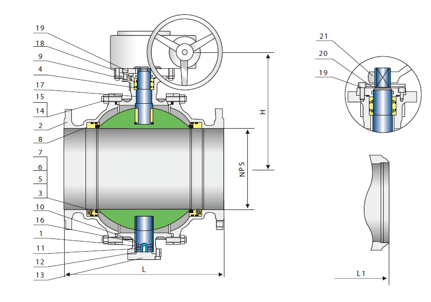
| No | Part Name | Carbon Steel | Stainless Steel 18Cr- 9Ni- 2Mo | Duplex SS | Carbon S teel |
| 1 | Body | A216- WCB | A351- CF8M | 4A/5A | A352- LCB |
| 2 | Bonnet | A216- WCB | A351- CF8M | 4A/5A | A352- LCB |
| 3 | Ball | A182- F304 | A182- F316 | SAF2205/2507 | A182- F304 |
| 4 | Stem | A276- 304 | A276- 316 | SAF2205/2507 | A276- 304 |
| 5 | Seat | A105+ENP | A182- F316 | SAF2205/2507 | A350- LF2+ENP |
| 6 | Seat Insert | Glass Filled PTFE | |||
| 7 | Seat Spring | A313- 304 | Inconel X- 750 | Inconel X- 750 | A313- 304 |
| 8 | Seat O- Ring | NPR | Viton | PTFE | Viton |
| 9 | Stem O- Ring | NBR????? 2) | Viton????? 2) | PTFE | Viton????? 2) |
| 10 | Bonnet Gasket | Graphite+304 | Graphite+316 | PTFE+2205 | Graphite+304 |
| 11 | Bonnet O- Ring | NBR | Viton | PTFE | Viton |
| 12 | Antistatic Spring | A313- 304 | A313- 316 | SAF2205/2507 | A313- 304 |
| 13 | Lower? Cover | A216- WCB | A182- F316 | SAF2205/2507 | A182- F304 |
| 14 | Bonnet Stud | A193- B7 | A193- B8 | A193- B8 | A320- L7 |
| 15 | Bonnet Stud Nut | A194- 2H | A194- 8 | A194- 8 | A194- 4 |
| 16 | Trunnion | A276- 304 | A276- 316 | A276- 316 | A276- 304 |
| 17 | Trunnion Bearing | 304+PTFE | 316+PTFE | 316+PTFE | 304+PTFE |
| 18 | Gland Flange | A216- WCB | A351- CF8M | A351- CF8M | A352- LCB |
| 19 | Gland Bolt | A193- B7 | A193- B8 | A193- B8 | A193- B7 |
| 20 | Stop Plate | Carbon Steel+Zn | Carbon Steel+Zn | Carbon Steel | |
| 21 | Handle | Carbon Steel | |||
| Note:1)A105+ENP optional | |||||
| 2)Spiral wound construction. | |||||
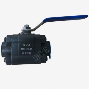
1.?Extended lever for easy operation?also available with gear box, motor?actuators, pneumatic or hydraulic?actuators.
2.?Split or 3-piece, split body & bolted Bonnet Design. This enables?easy disassemble of components for?repair.
3.?Full bore or reduced bore.Full boredesign provides exceptional flowcontrol.
4.??A choice of RF flanged,or RTJ flange ends? or buttweldends for piping flexibility.
5.?Standard packing vs.teflon packingcombined with live loading, maintainspacking compression under high cycleand sever service applications.Graphitepacking is used for high temperaturesituations.
6.?Anti-static – A metallic contact is alwaysgranted between ball and stem/bodyto discharge eventual static build-upsduring service.
7.?Fire safe designed to APl 607 orBS 6755 to ensure operation
sustainability in case of fire. Secondarymetal-to-metal seal acts as backup ifprimary seal is destroyed by fire.Valvesordered for compliance with APl 607will be provided with graphite packingand gaskets.
1. Valves should be stored in the open position. Valve ports and flange serration surfaces should be kept
sealed with protective flange covers.
2. Valves should be stored in a dust free, low humidity and well ventilated room, not in direct contact to
the floor. If possible, the valves shall be kept in the original packing box. If valves have to be storedoutdoors, keep the valve in the original crate or shipping container.Ensure the valve packaging is storedon raised blocking to avoid moisture damage. Protective covering should be used for protection againstdust and rain.
3. Valves should never be stacked on top of each other, to avoid any valve distortion which may affect
valve performance and cause personnel injury.
4. Valves that have been stored for an extended period of time should be cleaned and inspected prior to
installation. Inspect the sealing surface to ensure it is clean and free of any debris or damage.
5. Do not expose the valve to any corrosive environment as this may cause damage to the valve
components.
1 Before installation, check the valve nameplate and valve body information to ensure the valve issuitable for the intended service.
2 Before installation, remove the flange cover and the protective film on the flange sealing face, inspectthe ports and the flange sealing surface, remove any dirt with a clean soft cloth, use an anti-corrosivecleaning liquid to clean if necessary, and never use any other chemical products.
3 Inspect the flange gasket (including ring gasket) sealing surface and ensure it is in acceptablecondition for installation.
4 After cleaning the valve and before installation, open and close the valve one time. Ensure the valvecycles smoothly. If abnormal operation is experienced, stop the operation and inspect the valve internalsfor any obstructions that may be preventing normal operation.
5 After successfully cycling and assuring the proper operation of the valve, return the valve to the openposition and ensure the valve sealing surfaces are protected until installation is complete.
6.Position the valve into the pipe or the flange connection; ensure that any stresses caused by improperpipe alignment are relieved. Valves are not intended to be a means of aligning improperly fitted pipe.
7.Install the valve using qualified piping standards and practices. Valves marked with flow direction mustbe installed in line with the piping flow.
8.The recommended orientation for ball valves is upright with the valve in a horizontal line. The valvemay be installed in other orientations; however, any deviation from recommended horizontal position maycompromise proper valve operation and void the warranty.